Additional Engineering Projects
A Lifetime of Creations

Boeing 767-400 BPCU, GCU, BTB, TRU, APU
The prior engineer had failed to meet deadline after deadline, and the risks to the program had escalated to impacting major delivery schedules to the new Boeing 767-400 program. I went to the Program Manager and Project Manager and convinced them that I could right the program, but only if I could rapidly staff up with contractors I chose, and had full authority to take over the program. They agreed, and I knew my career with Hamilton Sundstrand was on the line!
I hired three contractors via phone interviews over the next two weeks, and fired one of the three on his first day because he didn't have the skills he purported. I worked with the two remaining engineers for several months to:
Analysis
Scrub the existing Failure Modes and Effects Analysis (FMEA) for errors
Perform the Testability Analysis against the corrected FMEA.
Design
Develop troubleshooting strategies
Identify locations for test points, and how to implement boundary scan
Verified critical faults would enunciate, and that enunciation would indict the correct unit
The Results: Recovered failing program to Hamilton Sundstrand's and their customer, Boeing's needs.
Reduced potential for incorrect black box removals from aircraft and Test OK (TOK) warranty return costs. Boeing was finally a happy customer.
The following paragraph adds context around the work on this project...
"There are two generators in the aircraft that serve as a primary power sources (shown as L-Gen and R-Gen in Figure 1). Each of them provides power to their respective AC Bus through a Generator Control Breaker (GCB), which is controlled by a local Generator Control Unit (GCU). Next, each AC Bus powers the local DC Bus through a Transformer Rectifying Unit (TRU). The Bus Power Control Unit (BPCU) controls the Bus Tie Breakers (BTB), which in the event of main generator failure, the BTB allows for the other generator, Auxiliary Power Unit (APU) or the External Power (EXT) to compensate for the lost generator. Similarly, the DC Tie allows one DC Bus to compensate the other in the event of a TRU failure. Lastly, the Left DC Bus or the onboard batteries can power the Battery Bus. This primitive functionality was incorporated into SysML as described in the next section."
Photo: Simplified 767 Electrical Power System (EPS) from web reference.
Aircraft Auxiliary Power Unit Test Cell
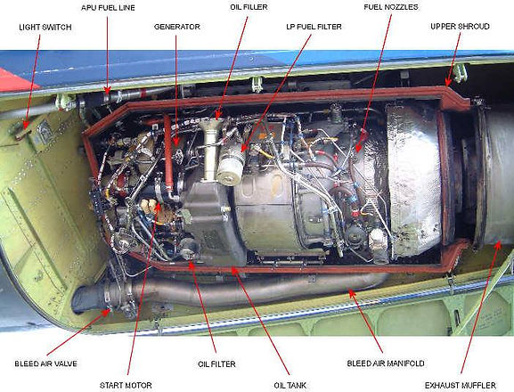
Not to be confused with the Space Shuttle APU test cell work I did (discussed elsewhere), Test Cell 137 was designed to test Auxiliary Power Units (APU) for large commercial aircraft. These units typically reside in the back of the aircraft and are used when the main engines are down on the tarmac, or when there are in-flight outages with one of the engines.
My role was to do a complete system redesign and overhaul of the test cell, including the Data Acquisition (DAQ), monitoring, reporting, analysis, and command & control systems.
In this year-long project working for the Director of Advanced R&D, Martin Lurvey, I built the LabVIEW command and control systems, selected, ordered, and built the SCXI signal conditioning system and PXI control systems, torque/speed measurements, and worked with embedded controllers and facility controls.
The system consisted of two primary approaches. (1) GPIB based data collection and (2) Data Acquisition systems.
Signal Generation & Controls
GPIB Controlled Function Generator
GPIB Controlled Voltage Source
Measurements Via Automated COTS Equipment
GPIB Controlled Voltech 3 Phase Power Meter
GPIB Controlled Oscilloscope
Measurements Via DAQ & SCXI
Thermocouples & Thermistors
Pressure Sensors
Strain Gauges
Frequency Counters
Voltage and Current Measurements
Command & Control
Digital I/O
Relay Controls
AC & DC Switched Outputs
GPIB Controlled Dynamometer & Dyno Controller
Photo: Sundstrand APS 2000 APU, one of the many APUs tested in Cell 137.

Wind Tunnel - Aircraft Ram Air Turbine (Emergency APU)
Rebuilt the Plant 7 East Wind Tunnel's Data Acquisition (DAQ) System, command and control system using LabVIEW, PXI, and SCXI signal conditioning modules. Responsible for the entire software control design system and signal management as the sole engineer for refurbishing the outmoded control system of the existing test cell.
Hardware
New host PC and Hardware Setup
New SCXI signal conditioning installation and configuration
Tied into existing PXI DAQ hardware
Software
Reused my Alarm Monitoring code from the Space Shuttle test cells
Created custom CSV based templates to load operating parameters for testing each type of unit (ex. Embraer, Boeing, A300, A320, Dornier-Fairchiled, Dowty Hawk, Global Express, Nimrod)
- New GUI and login processes
Created custom routines to dynamically load correct data channels needed for specific tests
Created new sequencing system to manage test progression
Ram Air Turbines (RAT) are propeller driven generators that can provide large commercial aircraft with minimum electric or hydraulic power in a worst-case scenario. They drop out of the nose area and enter the airstream. This wind tunnel was used to test the RATs.
NOTE: Representative picture of a Ram Air Turbine in a wind tunnel from web reference; no actual photo of the wind tunnel I built the controls for is available.

Switched Reluctance Motor Patent Assistance
I worked directly for the Engineering PhD, Yue Li, at Emerson Motor Company's Advanced Technology Center (ATC) on the development of prototypes and custom motor control signals and high-power MOSFET motor controller system fabrication that directly led to this patent. "Low cost drive for switched reluctance motor with DC-assisted excitation."
The idea was to "inject" DC current into an AC system at the right locations and timing to create additional rotational momentum. Motor controllers had just recently become fast enough for SRM to be a reality because of the complex drive signals required. I was working other SRM's for washers and dryers), but this was "next level" research.
Hardware
Built custom motor prototypes
Performed all testing and analysis
Built the high-power controller
Troubleshot failures
Implanted every idea our PhD came up with (which led to a lot of failures and troubleshooting!)
Software
Worked with programmable motor controller algorithms
Photo: One of the electrical diagrams from the patent showing the interactions of the high-power DC current injections.
Dynamometer Control Motor Test Stand
Emerson Motor Company's Advanced Technology Center (ATC) built a lot of prototype motors that were fragile, one of a kind, and very expensive. The testing took hours to characterize just one motor under load, and that testing often overheated the motor rendering it unusable.
I build a completely new approach using LabVIEW programming and a suite of GPIB controlled COTS equipment.
Hardware
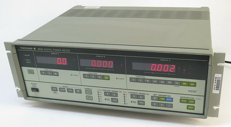
Yokogawa 2533 Three Phase Power meter
Magtrol 5420 Dynamometer Controller
Stanford Research Systems Model SR630 16 Channel Thermocouple Monitor
Agilent 4 channel Oscilloscope
Software
Created custom GPIB interfaces to all hardware devices
Designed LabVIEW based command and control, heavily dependent upon GPIB equipment
Used LabVIEW based interfaces to Microsoft Office report generation tools to automate reports
Results: By fully automating the load applied to the motor, picking up the torque measured through GPIB, capturing key scope and voltmeter snapshots automatically throughout the test, and exporting organized data to Excel, the stand could now do in 30 seconds what had taken 2-3 hours to complete previously... generate a complete torque-up and torque-down hysteresis curve.
And more importantly - preserve our prototype motors from overheating!
This was the effort that launched me into building and testing systems professionally for the rest of my career.
Picture: Yokogawa 2533 Three Phase Power Meter

Wind Tunnel, Fractional Horsepower Fan Motors
Maintained the Emerson Motor Company, Advanced Research Center, fractional horsepower wind tunnel. This LabVIEW controlled system inspired me to begin automating many of the test systems at Emerson.
NOTE: Representative picture of a fractional horsepower wind tunnel from web reference; no photo of the systems I worked is available.

Spearfish Torpedo Test Cell
I served in a supporting role on a near end-of-life Spearfish Torpedo engine test cell.
Troubleshooting
Maintenance

Trident 2 Missile Test Cell
I served in a supporting role on the Trident 2 Thrust Vector Control test cell.
Troubleshooting
Maintenance